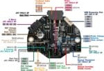
LDO Nitehawk 36 USB Toolboard (Rev. C)
Improved Revision C
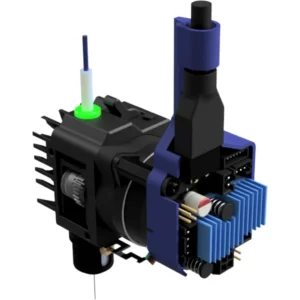
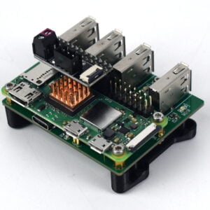
The LDO Nitehawk 36 USB Toolboard is featuring a RP2040 MCU, TMC2209 stepper driver, ADXL345 accelerometer, and USB port. Nitehawk-36’s USB based connection method allows for a simple and easy setup compared to other CAN tool boards. The USB connection also allows for a secondary USB port to connect your nozzle webcam or eddy current probe.
Features
- Convenient wiring, no more complicated and error prone breakout cables – Nitehawk only requires 24V power and a USB connector to the RPI host.
- USB Klipper connection, no additional software or hardware setup compared to CAN.
- Secondary USB port, an onboard USB port allows you to connect a second USB device to your toolhead without running an additional umbilical cable.
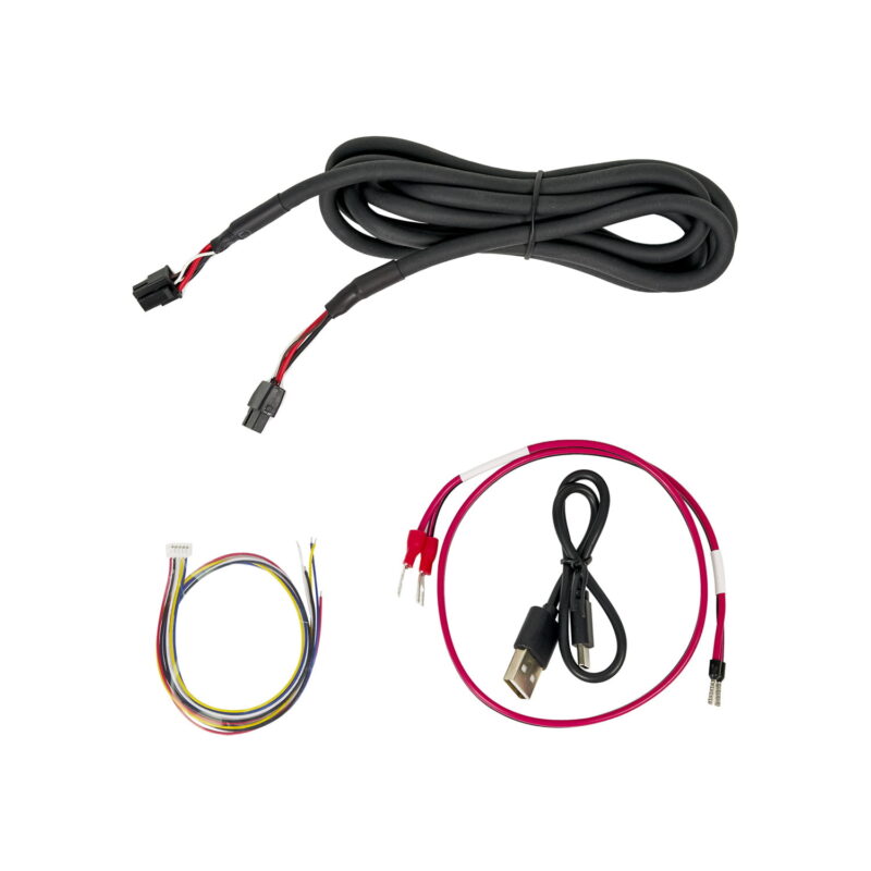
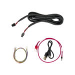
- Custom toolhead cable, a single combined USB data and power cable rated for drag chain use, but can also be used in umbilical configuration.
- Convenient Input Shaping, run input shaper calibration at anytime with an onboard accelerometer.
- Tacho enabled HEF, the hot end fan port is three pin tachometer compatible, allowing for additional diagnostics and safety.
System Overview
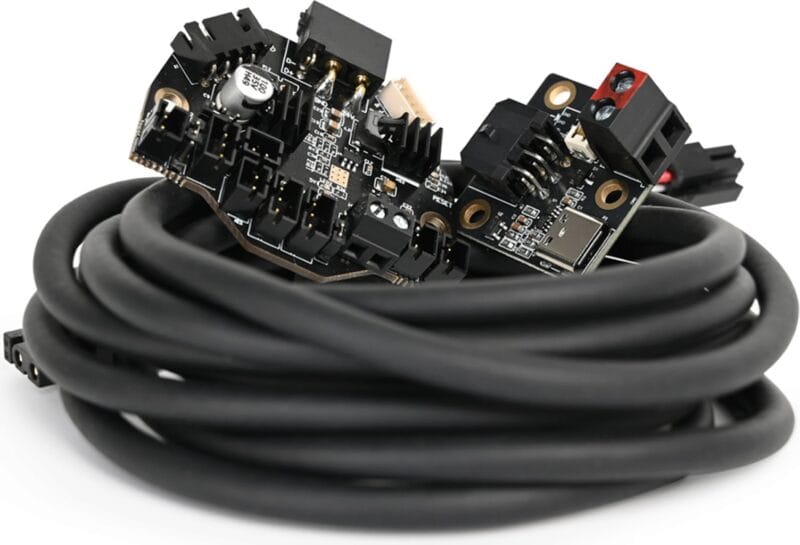
The LDO Nitehawk 36 USB Toolboard system consists of two PCBs and the Umbilical Cable. A simplified wiring diagram is shown below:

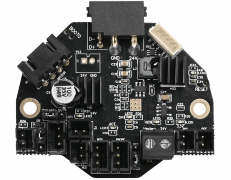
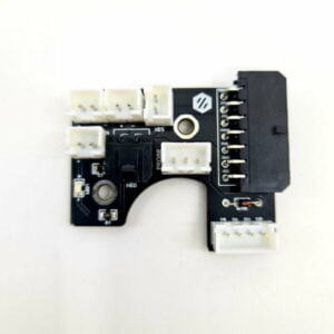
- Nitehawk-36, this is the main PCB, which houses the MCU, stepper driver, fan drivers, and other circuits.
- Umbilical Cable, this is a custom flex cable that is rated for drag chain use. It delivers 24V power to the main Nitehawk PCB while also carrying USB data.
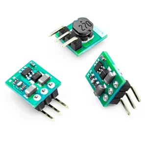
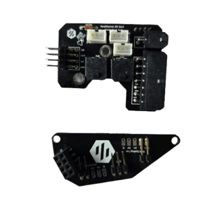
- USB Adapter, this simple PCB combines 24V power from the power supply and USB data from the Raspberry Pi into a unified connection to the main Nitehawk PCB via the Umbilical cable.
Harness Installation
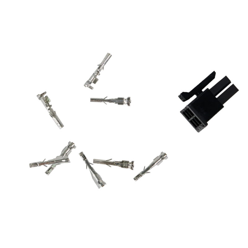
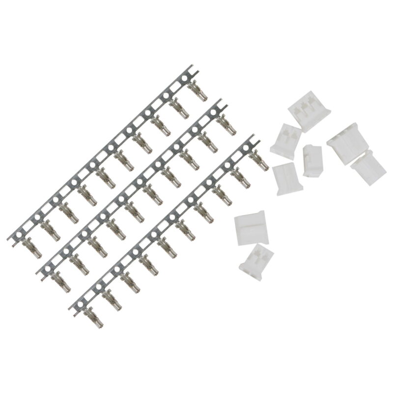
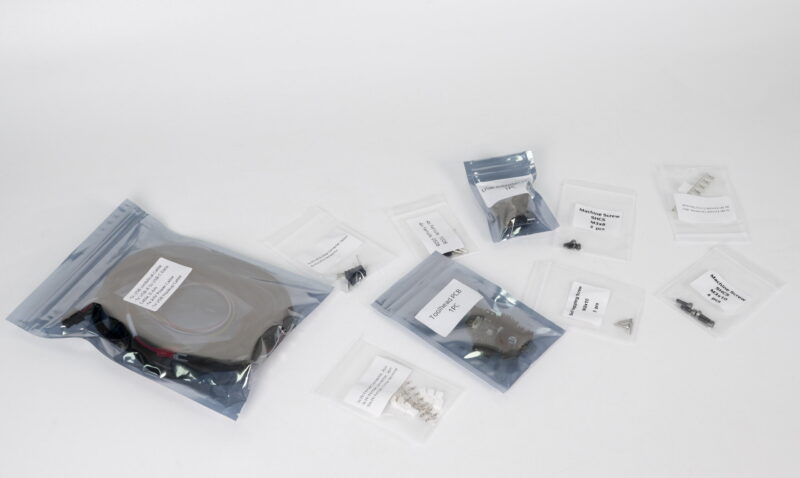
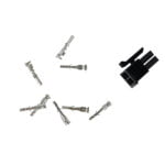
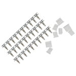
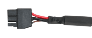
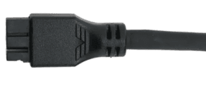
Rev C Nitehawk 36 will be shipped with a mix of molded and non-molded harnesses. Please make sure to tie down the harness between the connector and “moving bit” of the harness. Especially for the non-molded version make sure to leave enough slack between the tying point and the connector to de-couple the connector from the moving harness.
Printed Parts
The printed part is available in the Nitehawk github repo here.
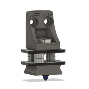
- USB Adapter Mount, this is the mount for the USB adapter PCB. It is designed to be used with a standard Voron DIN clip and can be mounted in two different orientations. It also features a cover to reduce the chance of static discharge onto the PCB.
Klipper Config Files
A Klipper Configuration can be found in the LDO Nitehawk 36 Toolboard github repo here.
Port and Pin Definitions
| Device/Port | PCB Label | Connector Type | RP2040 Pin | Description |
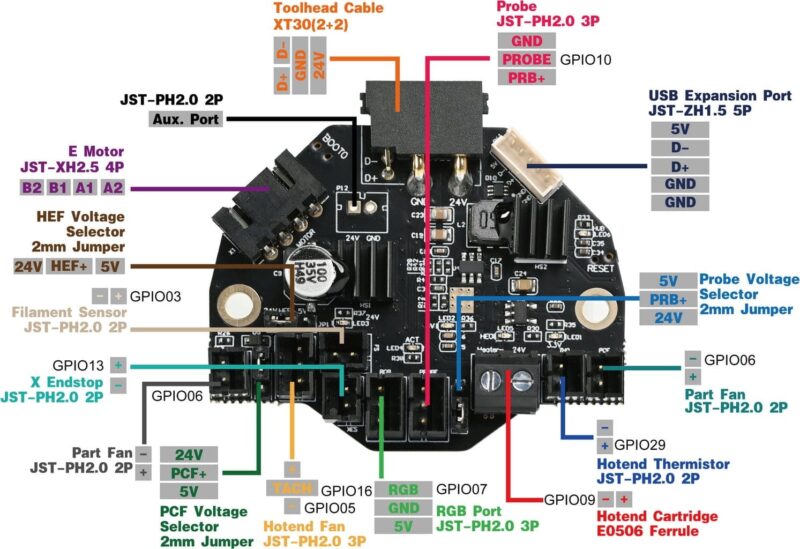
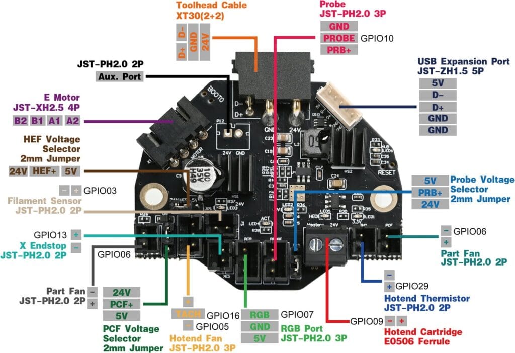
| E Motor | MOTOR | JST-XH2.5 4P | gpio23/24/25/0/1 (step/dir/ena/uart/tx) | A stepper motor port for the extruder. Driven by a TMC2209 chip. The current sense resistor is 100 mΩ. Enable is active low |
| Filament Sensor | JST-PH2.0 2P | gpio3 | Connects to the filament sensor. Supports switch based sensors only. | |
| Probe | PRB | JST-PH2.0 3P | gpio10 | Probe for bed levelling and/or Z sensing. 24V power only. |
| X Endstop | X-STOP | JST-PH2.0 2P | gpio13 | Connects to the X endstop. Supports switch based endstops only. |
| Part Fan | PCF | JST-PH2.0 2P | gpio6 | Connects to part cooling fan. |
| Hotend Fan | HEF | JST-PH2.0 3P | gpio5/16 (fan/tacho) | Connects to hotend fan. The fan control pin is gpio5 and the tachometer sensor pin is gpio16. |
| PCF Voltage Selector | 2mm Jumper | Selection of 24V or 5V. | ||
| HEF Voltage Selector | 2mm Jumper | Selection of 24V or 5V. | ||
| Probe Voltage Selector | 2mm Jumper | Selection of 24V or 5V. | ||
| USB Expansion Port | JST-ZH1.5 5P | Connects to USB expansion board. | ||
| Neopixel | JST-PH2.0 3P | gpio7 | Connects to Neopixel LEDs. | |
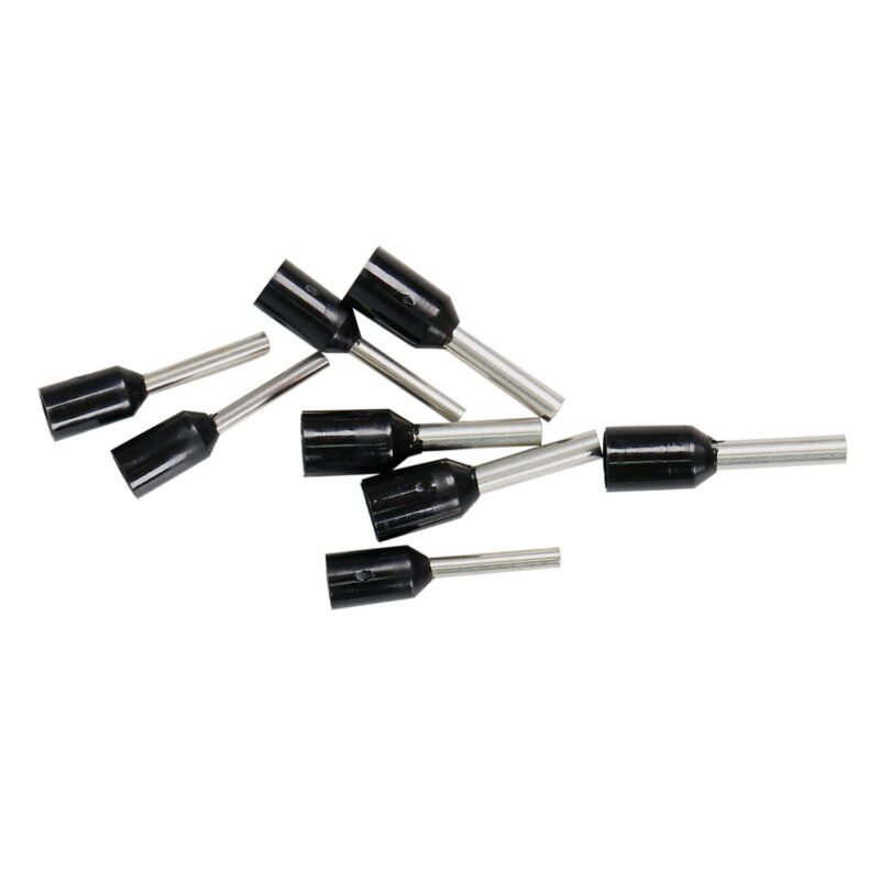
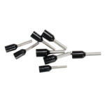
| Hotend Heater | HE0 | E0506 Ferrule | gpio9 | Connects to the hotend heater. |
| Hotend Thermistor | TH0 | JST-PH2.0 2P | gpio29 | Connects to the hotend thermistor. Uses a 2.2kΩ pull up resistor. |
| Activity LED | ACT | gpio8 | A small software controlled onboard LED. Active low. | |
| Accelerometer | gpio27/18/20/19 (cs/clk/mosi/miso) | ADXL345 accelerometer for input shaping. Controlled via software SPI. | ||
| Toolhead Cable | XT30(2+2) | A USB port for toolhead. |
Electrical Specifications
| Parameter | Symbol | Minimum | Typical | Maximum | Unit | Comments |
| Power Supply Input | Vin | 20 | 24 | 28 | V | power input for the toolboard. |
| Temperature | Tenv | 60 | ℃ | operating ambient temperature | ||
| 5V Current | Irpi | 5 | A | current output for the 5V buck converter. | ||
| Fan Current | Ifan | TBD | A | current rating for each fan port (HEF and PCF). |
Firmware Setup & Update
See instructions on the LDO support pages
